
Optimized Hot Runner Systems Deliver Improved Color Change Performance
As brands market greater variety, require shorter production runs, and change designs more frequently in consumer packaging and other applications; there is increased focus on changing color at processing. To maximize productivity and profit, processors understand the need to examine their processes and procedures to optimize color change performance.
Hot runners can play a major role in optimizing the injection molding color change process. We will outline the concepts that impact color change and examine how they influence a hot runner’s design. We will also look at the benefits of color change sequencing and the emergence of new hot runner technologies that can be leveraged to reduce color change time. Finally, we will examine several case studies which illustrate how real-world modifications in hot runner solutions can significantly improve color change performance.
A process run’s collection of ejected parts, changing from blue to white.
For Brand Owners, Color is King
To many large brand owners and OEMs color is a key differentiator, central to consumer appeal and product identity. For example, this can be observed in beverage packaging with a specific shade of red used for Coca-Cola while a specific shade of blue identifies Pepsi. As a result, many consumer-focused companies can be extremely sensitive about color, as it is tightly woven into their iconic brand image.
Outside our industry, color change may seem simple and have little need for concern. Replace the old color with the new, and keep making product – how hard can it be? Naturally, the complexities of manufacturing eliminate the ease. Material must be cycled through the melt delivery system, replacing material of one color with material of a different color. While it would be convenient and efficient to replace color in a single shot, it is highly unlikely due to the nature of the product and equipment. Downtime and scrapped material are a given when changing color to meet the requirements of a customer and brand. A poor color change process can result in extra wasted material, greater downtime, and increased scrap. These all translate to higher production costs.
Two Viewpoints on Volume
It is important to clarify how hot runner volume can be measured in two different ways. The first type of volume is “melt volume.” Melt volume is measured in conventional units like cubic centimeters or cubic inches. This is the unit of volume we work with in our everyday lives. This considers the total volume of melt in the entire hot runner. The second type of hot runner volume is “shot count” and measured in shots. This considers the number of shots needed to travel from the entry of the sprue to the gate entering the cavity. Hot runner shot count is directly dependent on the molding application, specifically part weight and mold cavitation, which make up the shot size. Hot runner shot count is also related to a hot runner’s melt volume. For example, if a hot runner is interchangeable between two molds, the hot runner’s melt volume stays the same for both applications. The mold with heavier parts will decrease the hot runner’s shot count. While shot count can be calculated in fractions of a shot, it can only be experienced in whole numbers. Like everything in our industry, neither system attribute is concrete, but best used to make considerations and comparisons.
Concepts and Considerations for Changing Colors
The first concept or consideration for hot runners and color change is to minimize replaced volume. Smaller things are easier to move than larger things. This also rings true for the volume of molten plastic inside a hot runner – a smaller residence volume of molten plastic inside the hot runner is easier to displace than a larger residence volume. This volume is most directly managed by the hot runner’s melt channel size, as there typically few options to consider when it comes to a hot runner’s optimal melt path layout. It is easy to minimize melt channel size, but decreasing size typically means an increase in pressure. During hot runner design, melt channel size must be carefully considered based on the resin, expected processing conditions, and known equipment limits.
This graphic shows the machine nozzle interfaced with a hot runner’s sprue bushing. The top shows a matching melt channel interface, while the middle and bottom show mismatches and their potential melt stagnation areas.
The second concept or consideration is to minimize or eliminate of dead spots or “no flow” areas in the melt path. In these areas old color might snag, pool, or hide and be difficult to move through the melt stream. Old color in these stagnant areas may unexpectedly burp or bleed into the melt stream during production of the new color, making reject parts. Material in the stagnant area may also degrade due to heat exposure and cause streaks. These risks are not just specific to the hot runner, as the melt channel diameters at the hot runner sprue and machine barrel interface should also align and match as closely as possible.
The third concept or consideration is to follow a procedure and set expectations. It is generally known that many variables can affect color change and influence the ability to meet expectations. Process settings can help color change greatly, so it is important to know if they can be changed. Designing a specific color change schedule and procedure can directly manage the ability to meet these expectations. Overall, it is good to have a plan if you are planning to change colors.
How Hot Runner Gates and Nozzles Influence Color Change
An important influence on color change is the gate bubble’s melt volume. The gate bubble is the mass of molten plastic surrounding the nozzle tip, between the seal ring and the gate orifice. During processing, this area consists of resin which is neither fully solid or molten. The resin contacting the gate material is cool and highly viscous, thermally insulating the melt which flows from the nozzle through the gate. This volume of the bubble depends on the nozzle design and gate style. It may have a stagnant or “backflow” region that can hinder color change. This is an example where the previous color can hide or be difficult to displace. This volume can be minimized with a tip insulator. This is a piece made from a relatively soft material that withstands relatively high temperature and consumes the volume of the bubble. With it, melt can be flushed out and replaced more quickly for faster color change. This adopts the first the second concepts of color change: reducing melt volume and eliminating stagnant flow areas.
The gate bubble of most hot runner gates is the mass of molten plastic between the hot runner’s nozzle tip and the gate orifice.
A gate bubble is nearly unavoidable. Certain nozzle tip designs discard or “zero out” the gate bubble by sealing at the cavity interface. This eliminates the gate bubble altogether so no tip insulator is necessary as the melt flows directly into the cavity.
The nozzle at the left shows an assembly where the gate bubble is consumed by a tip insulator (brown). The nozzle at the right nullifies the gate bubble by participating as part of the cavity geometry.
How Hot Runner Manifold Design Influences Color Change
Another influence to color change with hot runners is the manifold design. This applies to any hot runner, regardless of nozzle or gating style. Manifold melt volume and shot count is a necessity for any hot runner application, with some manifolds containing more melt than others. That amount of material interferes with color change, as it must be replaced. The amount of molten material can be managed with melt channel diameter. To change color, this can be done faster if the amount of material to be replaced is minimized. However, a hot runner design must also consider the pressure requirement of the application. While volume (melt channel diameter) should be minimized, it should not be so far that the pressure limit of the machine’s injection unit is exceeded.
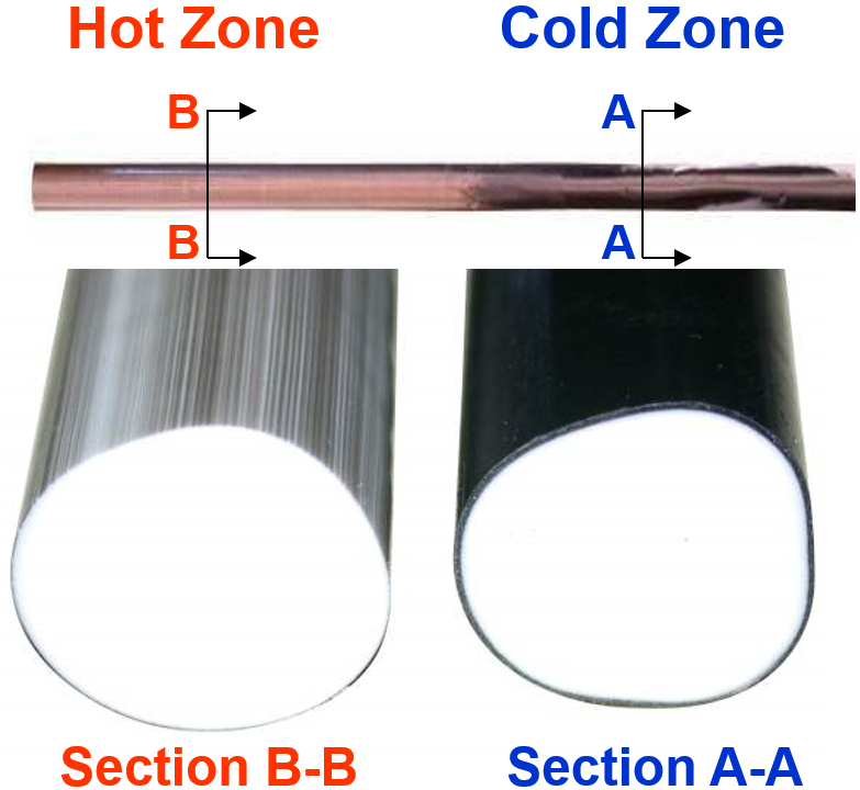
This graphic shows solidified plastic removed from a manifold melt channel after a few cycles of black-to-white color change. The hotter location (left) shows a thinner layer of old color than the colder location (right).
Thermal profile is another factor to consider when designing manifolds for color change. In addition to influencing injection pressure, a uniform thermal profile minimizes cold spots where the plastic boundary layer thickness at the melt channel wall can increase. The increased thickness at this cold location can cause difficulty when changing color, acting like a “dead spot” from the second concept.
Based on field experience and thorough analysis, Husky has developed robust manifold heater guidelines and applies them to all custom hot runner systems. By consistently applying these guidelines, thermal variation is minimized along the entire melt path. Thermal profile is also optimized by adjusting heater wraps, number of heater zones, thermocouple placement, melt channel layout, heat sink position, and manifold shape. The combination of these variables is validated by using finite element analysis to ensure minimal thermal variation. All of Husky’s manifold designs are FEA validated for thermal profile.
How Hot Runner Manufacturing Influences Color Change
The hot runner’s manifold manufacturing is the final influence on color change. While the first two influences on color change cover application and component design, manifold manufacturing focuses on how the product is taken from the concept to the press. Thermal uniformity is an important consideration and one way to minimize variation is through automated heater installation. This ensures consistent performance from each zone and each manifold. In addition to resistance checks and power testing at final assembly, another way to validate manifold heaters is by using thermal imaging.
Manufacturing has a major impact on minimizing dead spots in the melt flow path. Husky examined the effectiveness of manifold manufacturing systems by measuring and comparing the color change timing of sample parts with various build conditions and resins. Husky tested manufacturing influences by building several manifolds with different levels of variation, running color change procedures, and comparing their performance. The results showed the best color change was achieved by applying our principles, gating, and minimizing manufacturing variation.
Investment in Color Change Sequencing Pays Dividends
Color change is dependent on many things, one of which is the color itself. Each color typically requires different amounts of material to change from one to another. While it is relatively fast to change from dark colors to light colors, the other way around usually requires more material. It is important to develop an understanding of the part and colors required for each application, even running trials to understand the color change needs for each color across the product matrix. Production planning is one of the most effective ways to execute color change. This can be done by planning to run colors in a set sequence, typically gradual color change from dark to light and back to dark, leveraging schedule and equipment on the production floor. This element of color change performance seems obvious but is often overlooked. If production allow some flexibility, the order of color change can have a substantial impact on resin usage and downtime. For example, in one case study a molded closure not optimized for color change took 57.6 kg of material to complete a full color change cycle. By changing the run order of those same colors, color changeover was reduced from 600 to 400 shots and resin usage was reduced 33%. If this information and flexibility is available, production scheduling can take advantage of both to maximize productivity.
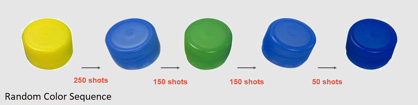
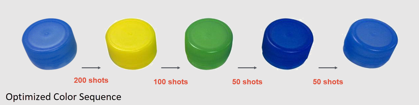
Many parts are molded with the same mold, hot runner, and material - but different colors. The top sequence above used a haphazard color plan. The bottom sequence used an optimized color plan, with a color change downtime reduction of 33%. Turnover between colors should be studied at validation to confirm when the best sequence to minimize operation costs.
Beyond the Hot Runner
Along with hot runner design considerations and scheduling, other technologies can be leveraged to decrease color change time. A system-based approach includes the injection molding machine and hot runner temperature controller working together to deliver more consistent and efficient color change when using purging compounds. By utilizing the Husky Altanium controller and its large touchscreen monitor, color change instructions can be integrated into the Altanium software and provide precise guidance at the user’s fingertips.
Additional features such as soak timers and automatic temperature adjustments coupled with cycle count input from the molding machine and automated optimized procedures, can ensure correct steps are followed every time. This delivers consistent and optimized results no matter the machine or the experience level of the operator.
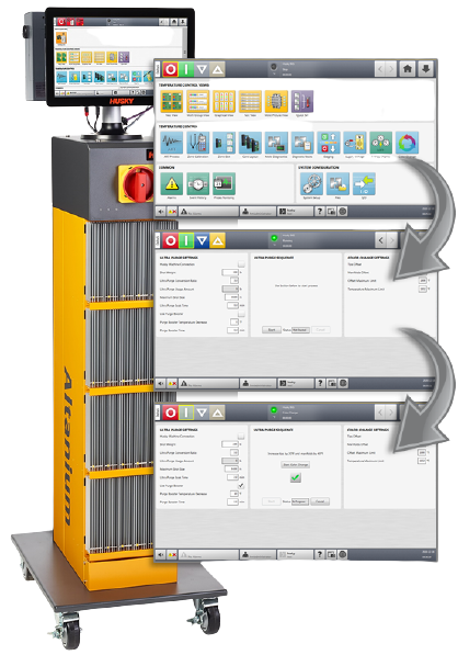
Altanium temperature controller features can be utilized to streamline color change processes.
Case Studies
A pair of case studies illustrate how hot runner features can be optimized for improved color changeovers. On a 32-cavity polypropylene closure mold, changing from amber to natural color required up to nine thousand cycles in 28 hours until a part of acceptable color was produced. Husky implemented adjustments and changes which reduced the color changeover to 215 cycles in 40 minutes. This saved over 22,000 pounds of scrapped material and more than 650 hours of machine time.
In another case study, a two-shot eight-cavity mold undertook one of the most challenging color changes, going from black to white with two different grades of polypropylene. After modifications and changes, color change time was reduced from 1100 cycles to 240 - saving over five thousand pounds of material and 150 hours of machine time per year.
Conclusion
Color change optimization clearly delivers significant value in terms of productivity and profitability. As brand owners and OEMs continue to focus on consumer appeal and product differentiation, processors of injection molded parts will seek the best optimization strategies to improve color changeover times. Optimized hot runner systems stand ready to meet the challenge with improved designs, manufacturing methods, and new technologies that will keep color change a step ahead in injection molding.