
To install an Ultra Nozzle Heater (UNH) with a ring thermocouple, do the following:
- Install new wave springs over the nozzle housing and nozzle tip.
Figure 1. Ultra Nozzle Heater (UNH) Assembly With a Ring Thermocouple 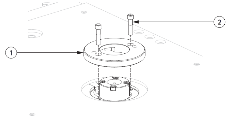
-
Retaining Clip
-
Ring Thermocouple
-
Ultra Nozzle Heater (UNH)
-
Nozzle Tip
-
Wave Spring
-
- Install the retaining clip on the nozzle tip and pull the nozzle heater and ring thermocouple up against it.
Important:
Make sure the retaining ring is snapped fully into the retaining clip groove around the whole diameter of the nozzle tip. Refer to the following figure.
Figure 2. Retaining Ring in Nozzle Tip Groove 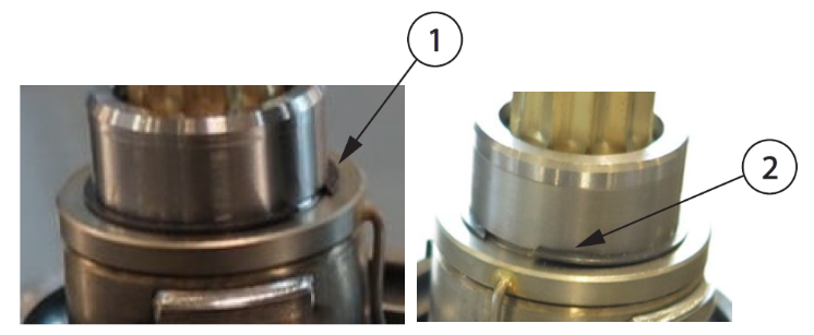
-
Retaining Clip Fully Seated in Groove (Correct)
-
Retaining Clip Not Fully Seated in Groove (Incorrect)
CAUTION:Mechanical hazard – risk of damage to the hot runner. Do not bend the nozzle heater wires at a 90° angle. Do not bend the nozzle heater wires directly at the lead exit of the heater body. The wires will crack or break over time.
-
- On U750 heaters, bend the nozzle heater wires in an arc against the heater body. Make sure each bend has a minimum 10 mm (0.4 in) radius.
Figure 3. Ultra Nozzle Heater - U750 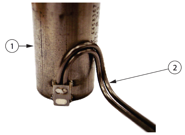
-
Ultra Nozzle Heater
-
Nozzle Heater Wires
-
- On U500 heaters, first bend the leads along the curvature of the heater, and then bend them up or down (away from the lead exit of the heater body) to meet the manifold plate wire groove as required.
Figure 4. Ultra Nozzle Heater - U500 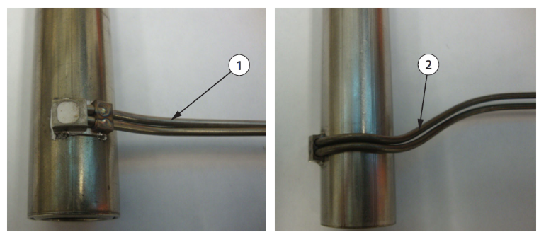
-
Heater leads before bending
-
Heater leads after bending
-
- Route the nozzle heater and thermocouple wires through the wire channels in the manifold plate. Make sure all wiring is properly retained in the wire channels using wire spring clips. Make sure of the following:
- The heater and thermocouple spring back to the retaining ring and maintain contact with each other after being pushed down (0.5 to 2mm) on the housing. See the following figure.
Figure 5. Heater/ Thermocouple Spring Back to Retaining Ring 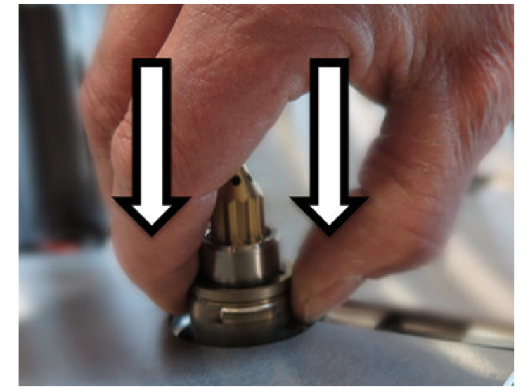 Note:
Note:If the heater and thermocouple do not spring back to the snap ring or maintain contact with each other, the bends in the wiring may be at fault.
-
Wire routing must not over constrain heater positioning on nozzle.
-
Wiring contacting a wire groove clip can restrict spring-back motion.
-
Adjust wiring by pushing it down towards the bottom of the wire groove.
-
Wiring must not protrude above the plate surface.
Figure 6. Wiring Placement in Groove 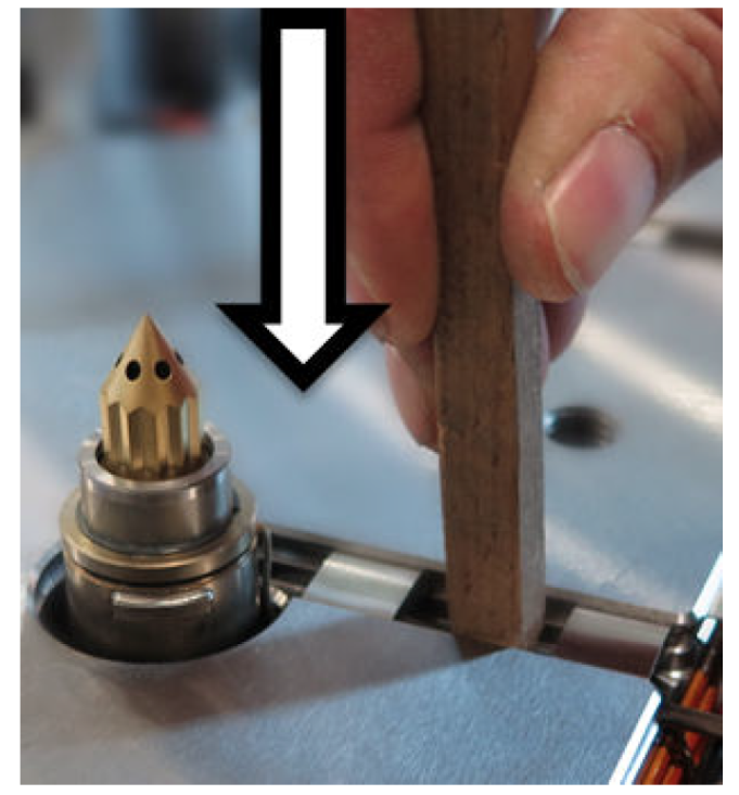
Note:Proper operation of the Ultra Nozzle Heater requires the force of the wave spring to maintain contact between the thermocouple ring and nozzle heater. Improper installation may result in processing issues.
-
- The heater and thermocouple spring back to the retaining ring and maintain contact with each other after being pushed down (0.5 to 2mm) on the housing. See the following figure.
- Make sure to stagger the knuckles in the wire grooves.
Figure 7. Staggering the Knuckles in the Wire Grooves  Note:
Note:All wire, including heater or thermocouple wire, that could contact a heated component such as a nozzle housing or manifold must be mineral insulated high temperature wire (hard lead). If the mineral insulated lead is not long enough to allow this, additional steps must be taken, such as using high temperature sleeving, to prevent the knuckles and PTFE or Kapton insulated wire (soft lead) from overheating.
Why order through the Husky Spare Parts Portal?
- Access to online spare parts promotions
- Order genuine Husky Replacement parts anytime, 24/7
- Quickly find the parts you need
- Access your order history and track deliveries online
Need Help with Spare Parts or Preventive Maintenance Kits for Your Hot Runner?
Fill out the form below and our team will contact you.